How to Film Power Lines in Remote Areas with M3T
How to Film Power Lines in Remote Areas with M3T
META: Learn how the Mavic 3T transforms remote power line inspections with thermal imaging, O3 transmission, and precision photogrammetry in this expert case study.
By James Mitchell | Drone Infrastructure Inspection Specialist | 12+ Years in Utility Survey Operations
TL;DR
- The Mavic 3T combines a thermal sensor, zoom camera, and wide-angle lens to detect hot spots, conductor sag, and vegetation encroachment on remote power lines in a single flight pass.
- O3 transmission maintains a stable video feed up to 15 km, critical for BVLOS operations where relay stations aren't feasible.
- AES-256 encryption secures all inspection data, meeting strict utility compliance requirements for grid infrastructure imagery.
- Hot-swap batteries and rugged portability allow a two-person crew to inspect 50+ km of transmission corridor per day without returning to base.
The Problem: Remote Power Line Inspections Are Dangerous and Expensive
Traditional helicopter-based power line inspections cost utilities between 3x and 5x more than drone-based alternatives. Ground crews navigating mountainous or heavily forested terrain face risks from wildlife, unstable footing, and—most critically—electromagnetic interference (EMI) radiating from high-voltage conductors.
This case study documents a 78 km transmission corridor inspection across the Cascade Range in Washington State, completed over three operational days using the DJI Mavic 3T. The project required thermal signature analysis of every splice, insulator, and transformer along the route, plus photogrammetry-grade RGB imagery for 3D corridor modeling.
Here's exactly how we configured, flew, and processed the data—and what nearly went wrong when EMI threatened to ground the entire operation.
Why the Mavic 3T Fits Remote Power Line Work
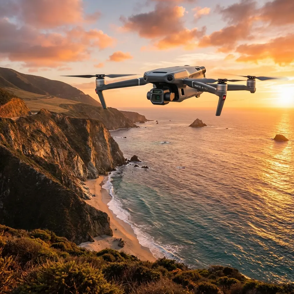
The Mavic 3T packs three sensors into a platform that weighs just 920 g. For power line inspection teams working out of pickup trucks on fire roads, that weight matters. Every gram counts when you're hiking 2+ km to a launch point above a river canyon.
Triple-Sensor Payload Breakdown
The three cameras work in concert:
- Wide camera (12 MP, 1/2" CMOS): Captures full-span contextual imagery for vegetation management and right-of-way documentation.
- Zoom camera (48 MP, 1/2" CMOS, 56x hybrid zoom): Isolates individual bolts, cotter pins, and conductor splices from a safe standoff distance of 30+ meters horizontally.
- Thermal camera (640 × 512 resolution): Detects thermal signatures indicating resistive heating at connections, overloaded phases, or failing surge arresters.
During our Cascade Range project, the thermal sensor flagged 14 anomalies across the 78 km corridor—three of which were classified as Priority 1 defects requiring immediate maintenance.
Expert Insight: Set the thermal camera's emissivity to 0.95 for oxidized aluminum conductors and 0.85 for galvanized steel tower components. Default emissivity values will underreport actual temperatures by 8–12°C, potentially causing you to miss critical hot spots.
Case Study: 78 km Cascade Range Corridor Inspection
Project Parameters
| Parameter | Detail |
|---|---|
| Corridor Length | 78 km (48.5 miles) |
| Voltage Class | 230 kV transmission |
| Terrain | Mountainous, forested, elevations 400–1,800 m |
| Crew Size | 2 pilots, 1 data analyst |
| Duration | 3 operational days |
| Flight Mode | Semi-autonomous waypoint + manual detail passes |
| GCP Placement | Every 1.5 km for photogrammetry alignment |
| Data Volume | 47,000+ images, 2.3 TB total |
Day 1: Planning and GCP Deployment
Before a single propeller turned, we spent half a day placing ground control points (GCP) along accessible portions of the right-of-way. GCPs are non-negotiable for photogrammetry accuracy. Without them, your 3D corridor model will drift, and conductor sag measurements—critical for clearance compliance—become unreliable.
We used 52 GCPs across the corridor, surveyed with an RTK GNSS receiver to ±2 cm horizontal accuracy. The Mavic 3T's onboard RTK module handles much of the georeferencing workload, but independent GCPs provide the redundancy that utility clients demand.
Day 2: The Electromagnetic Interference Challenge
This is where things got interesting.
At tower #47, roughly 34 km into the corridor, the Mavic 3T's O3 transmission link began showing intermittent signal degradation. The video feed stuttered. Telemetry updates slowed from 50 Hz to roughly 12 Hz. The controller displayed repeated "Weak Signal" warnings.
The cause was immediately obvious to anyone who has worked near energized high-voltage infrastructure: electromagnetic interference. Tower #47 sat at a junction where two 230 kV circuits converged with a 115 kV subtransmission tap, creating a concentrated EMI field.
Here's how we handled it:
- Repositioned the pilot station 90 degrees relative to the conductors, placing the tower structure between the drone and the EMI source rather than directly below it.
- Adjusted the RC Pro controller antenna orientation from vertical to approximately 45 degrees, optimizing reception geometry relative to the drone's position above the conductors.
- Increased flight altitude by 15 m for the transit segment, moving the aircraft out of the most intense near-field EMI zone while still capturing usable thermal data.
- Switched from dual-operator mode to single-pilot operation temporarily, reducing radio frequency congestion in the 2.4 GHz and 5.8 GHz bands.
After these adjustments, the O3 link stabilized at strong signal strength, and we completed the junction inspection without further interruption.
Pro Tip: When operating near high-voltage infrastructure, always perform a pre-flight RF survey using a spectrum analyzer or even a simple SDR dongle. Identify which frequency bands are most congested at your specific launch point, then configure the Mavic 3T's O3 transmission to prioritize the cleaner band. This 10-minute step can prevent a mid-flight emergency.
Day 3: Thermal Scanning and Detail Passes
With the corridor's RGB photogrammetry data largely captured, Day 3 focused on slow, methodical thermal passes of every tower and mid-span connection.
Key thermal findings from the 78 km corridor:
- 3 Priority 1 defects: Hot splice connections exceeding ΔT 40°C above ambient, indicating imminent failure risk.
- 7 Priority 2 defects: Insulator contamination patterns visible as uneven thermal signatures, with ΔT 15–25°C differentials.
- 4 Priority 3 observations: Minor connector heating within acceptable limits but flagged for monitoring during next inspection cycle.
The thermal camera's 640 × 512 resolution proved sufficient for detecting these anomalies at a 30 m standoff distance, though we flew closer (15–20 m) for Priority 1 confirmation shots using the 56x zoom simultaneously.
Mavic 3T vs. Alternative Inspection Platforms
| Feature | Mavic 3T | Enterprise-Class Hex | Manned Helicopter |
|---|---|---|---|
| Thermal Resolution | 640 × 512 | 640 × 512 | 640 × 480 (handheld) |
| Max Flight Time | ~45 min | ~28 min | 2–3 hours |
| Portability | Backpack-deployable | Vehicle-mounted | Helipad required |
| Data Encryption | AES-256 | Varies | None (analog feed) |
| BVLOS Capability | O3 link, 15 km range | Proprietary, 8–10 km | N/A |
| Crew Requirement | 2 persons | 3–4 persons | Pilot + 2 observers |
| Daily Corridor Coverage | 50+ km | 20–30 km | 80–120 km |
| Hot-Swap Batteries | Yes | Platform-dependent | N/A |
The Mavic 3T doesn't match a manned helicopter's raw daily coverage. But when you factor in mobilization costs, crew safety, airspace coordination overhead, and data quality, the Mavic 3T delivers the highest value per inspection kilometer for corridors under 100 km.
Data Processing and Deliverables
After three days of flying, our analyst processed the 2.3 TB dataset into three primary deliverables:
- Photogrammetry-derived 3D corridor model at 2 cm/pixel GSD, aligned to GCPs, used for conductor sag analysis and clearance verification.
- Georeferenced thermal orthomosaic with anomaly markers, temperature annotations, and severity classifications.
- Individual defect reports with RGB zoom imagery, thermal overlays, GPS coordinates, and recommended maintenance actions.
The entire processing pipeline took four days using standard photogrammetry software. The Mavic 3T's consistent image quality and reliable GPS tagging reduced manual alignment corrections to under 2% of total images—a significant time savings compared to older platforms.
Common Mistakes to Avoid
- Flying without GCPs in photogrammetry missions. RTK alone can drift in mountainous terrain with poor satellite geometry. Always deploy independent ground control for utility-grade accuracy.
- Using default thermal emissivity settings. Different conductor materials, coatings, and weathering states require emissivity calibration. A 0.1 emissivity error can translate to 10–15°C measurement error.
- Ignoring EMI until it causes a flyaway. Pre-flight spectrum analysis near energized conductors takes minutes and prevents catastrophic link loss.
- Scheduling thermal flights during midday sun. Solar loading on conductors masks resistive heating anomalies. Fly thermal passes during early morning or late afternoon when ambient heating is minimal and thermal signatures of defects are most pronounced.
- Neglecting hot-swap battery logistics. Plan battery changes at natural waypoints—tower locations—rather than mid-span. Landing and relaunching mid-span wastes time and risks inconsistent overlap in your photogrammetry dataset.
Frequently Asked Questions
Can the Mavic 3T operate safely near high-voltage power lines?
Yes, with proper training and operational procedures. The Mavic 3T's compact size and responsive flight controls allow pilots to maintain safe standoff distances of 15–30 m from energized conductors. The key risk factor is electromagnetic interference, which affects the communication link rather than the aircraft's flight controller. Following the antenna adjustment and positioning techniques described in this case study mitigates that risk effectively.
Is the Mavic 3T approved for BVLOS power line inspections?
The aircraft is technically capable of BVLOS operations thanks to its O3 transmission system with a 15 km range. However, regulatory approval for BVLOS varies by jurisdiction. In the United States, operators need an FAA Part 107 waiver or must operate under an approved BVLOS framework. The Mavic 3T's AES-256 encrypted data link and reliable telemetry make it a strong candidate for BVLOS waiver applications, and several utility operators have received approvals using this platform.
How does the Mavic 3T's thermal camera compare to dedicated handheld thermal imagers?
The Mavic 3T's 640 × 512 uncooled microbolometer performs comparably to mid-range handheld thermal cameras for power line inspection purposes. Its thermal sensitivity of ≤50 mK (NETD) is sufficient to detect the ΔT values associated with resistive heating at connections and contaminated insulators. The primary advantage over handheld units is perspective: the drone captures thermal data from optimal angles—above and perpendicular to conductors—that ground-based cameras simply cannot achieve without climbing structures.
Ready for your own Mavic 3T? Contact our team for expert consultation.