Mavic 3T Guide: Mapping Coastlines in High Winds
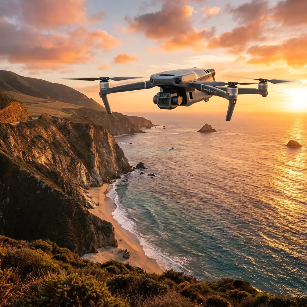
Mavic 3T Guide: Mapping Coastlines in High Winds
META: Master coastal mapping with the Mavic 3T drone. Expert tips for wind management, antenna positioning, and thermal imaging for accurate shoreline surveys.
TL;DR
- O3 transmission maintains stable connectivity up to 15km even in coastal wind conditions exceeding 12 m/s
- Optimal antenna positioning at 45-degree angles maximizes signal strength during extended shoreline surveys
- Thermal signature detection identifies erosion patterns and water intrusion invisible to standard RGB sensors
- Strategic GCP placement compensates for GPS drift common in dynamic coastal environments
Why Coastal Mapping Demands Specialized Drone Capabilities
Coastal mapping operations face unique challenges that ground most consumer drones. Salt spray, unpredictable gusts, and electromagnetic interference from breaking waves create hostile conditions for aerial surveys. The Mavic 3T addresses these obstacles through enterprise-grade engineering specifically designed for demanding environmental conditions.
Wind speeds along coastlines regularly exceed 10-15 m/s, with sudden gusts reaching 20 m/s during survey windows. Standard drones struggle to maintain position accuracy, resulting in blurred imagery and inconsistent overlap between flight lines.
The Mavic 3T's max wind resistance of 12 m/s provides operational headroom for most coastal conditions. Combined with its mechanical shutter on the wide camera, motion blur becomes negligible even during aggressive repositioning maneuvers.
Antenna Positioning for Maximum Coastal Range
Expert Insight: The single most overlooked factor in coastal drone operations is antenna orientation. I've recovered failing missions simply by adjusting controller position relative to the aircraft's flight path.
The O3 transmission system relies on four omnidirectional antennas embedded in the remote controller. While marketed as omnidirectional, real-world performance varies dramatically based on positioning.
Optimal Controller Orientation
For coastline mapping where the aircraft travels parallel to the shore:
- Position yourself perpendicular to the primary flight path
- Angle the controller screen at approximately 45 degrees from horizontal
- Avoid pointing antenna tips directly at the aircraft
- Maintain line-of-sight by positioning on elevated terrain when possible
During extended BVLOS operations approved under appropriate waivers, antenna positioning becomes even more critical. Signal degradation typically begins around 8km in coastal environments due to salt particle interference and humidity absorption.
Signal Enhancement Techniques
Consider these proven methods for extending reliable transmission range:
- Use a ground station antenna amplifier for surveys exceeding 10km
- Position the controller above waist height using a tripod mount
- Orient the controller's flat face toward the aircraft rather than edges
- Avoid metal structures within 3 meters of your operating position
Thermal Imaging for Coastal Analysis
The Mavic 3T's 640×512 thermal sensor transforms coastal mapping from simple photogrammetry into comprehensive environmental analysis. Thermal signature detection reveals phenomena invisible to standard cameras.
Applications for Shoreline Surveys
Erosion Pattern Identification
Subsurface water channels appear as distinct thermal anomalies. Areas with active groundwater seepage display temperature differentials of 2-4°C compared to surrounding substrate. These patterns predict future erosion zones months before visible changes occur.
Infrastructure Assessment
Seawalls, drainage systems, and buried utilities generate characteristic thermal signatures. The Mavic 3T's DFOV mode captures synchronized thermal and visible imagery, enabling precise correlation between surface conditions and subsurface thermal patterns.
Wildlife Monitoring
Nesting sites, marine mammal haul-outs, and bird colonies become immediately apparent in thermal imagery. Survey timing during early morning hours maximizes thermal contrast between organisms and ambient surfaces.
Pro Tip: Set thermal palette to "White Hot" for coastal surveys. Water appears uniformly dark, making shoreline boundaries and thermal anomalies immediately distinguishable during real-time monitoring.
Photogrammetry Workflow for Windy Conditions
Standard photogrammetry parameters require adjustment for coastal wind conditions. The following specifications optimize data quality while accounting for aircraft movement.
Recommended Flight Parameters
| Parameter | Standard Conditions | High Wind Coastal |
|---|---|---|
| Forward Overlap | 75% | 85% |
| Side Overlap | 65% | 75% |
| Flight Speed | 10 m/s | 6-8 m/s |
| Altitude AGL | Variable | 80-120m |
| Gimbal Pitch | -90° | -85° |
| Photo Interval | Distance-based | 2-second timed |
The increased overlap compensates for positional variance caused by wind gusts. Reducing flight speed allows the gimbal stabilization system adequate time to settle between exposures.
GCP Strategy for Dynamic Environments
Ground Control Points along coastlines face unique challenges. Tidal zones shift constantly, and sandy substrates provide unstable mounting surfaces.
Placement Recommendations:
- Position GCPs on stable rock outcrops or permanent structures
- Use weighted targets rated for wind speeds exceeding 15 m/s
- Establish a minimum of 5 GCPs per kilometer of coastline
- Survey GCP positions using RTK GPS with horizontal accuracy below 2cm
- Document tidal state at time of GCP survey and flight execution
Data Security During Field Operations
Coastal surveys often involve sensitive infrastructure or environmental data subject to regulatory protection. The Mavic 3T's AES-256 encryption secures all transmitted data between aircraft and controller.
Security Best Practices
Enable Local Data Mode to prevent any network connectivity during sensitive operations. This ensures complete data isolation throughout the survey mission.
For extended operations, hot-swap batteries enable continuous flight without powering down the aircraft. This maintains encryption keys and prevents potential vulnerability windows during restart sequences.
Store mission data on encrypted microSD cards and transfer to secure systems immediately upon returning from field operations.
Common Mistakes to Avoid
Ignoring Wind Direction Changes
Coastal winds shift rapidly. What begins as a manageable headwind can become a dangerous crosswind within minutes. Monitor wind forecasts continuously and establish abort criteria before launch.
Insufficient Battery Reserve
Fighting headwinds during return flights consumes dramatically more power than outbound legs. Maintain minimum 40% battery when initiating return sequences in windy conditions.
Poor GCP Distribution
Clustering GCPs near accessible areas creates geometric weakness in photogrammetric solutions. Distribute points across the entire survey area, even when placement requires additional effort.
Neglecting Thermal Calibration
The thermal sensor requires flat field calibration before each mission. Skipping this step introduces measurement errors that compound across large survey areas.
Single Flight Line Planning
Coastal features benefit from cross-hatch flight patterns. Single-direction passes create shadows and occlusions that reduce model accuracy along vertical surfaces like cliffs and seawalls.
Frequently Asked Questions
What wind speed is too high for coastal mapping with the Mavic 3T?
The Mavic 3T maintains stable flight in sustained winds up to 12 m/s. However, coastal gusts often exceed sustained readings by 50-100%. When sustained winds reach 8-9 m/s, expect gusts approaching the aircraft's limits. Abort operations when sustained winds exceed 10 m/s to maintain adequate safety margins for unexpected gusts.
How does salt spray affect the Mavic 3T's sensors and motors?
While the Mavic 3T lacks formal IP rating, its sealed motor design and coated electronics provide reasonable protection against salt exposure. After coastal operations, wipe all external surfaces with a damp microfiber cloth and allow complete drying before storage. Inspect gimbal bearings monthly for salt crystal accumulation, which manifests as grinding sounds during movement.
Can the thermal camera detect underwater features along coastlines?
Water absorbs thermal radiation within the first few millimeters of surface depth. The thermal sensor cannot image submerged features directly. However, thermal imagery reveals water temperature variations indicating current patterns, freshwater discharge points, and shallow areas where substrate influences surface temperature. These indirect indicators provide valuable coastal analysis data.
Ready for your own Mavic 3T? Contact our team for expert consultation.